Circuit adder bit logic ece generate truth table now diagram number Adder adders libretexts circuits pageindex Combinational circuit
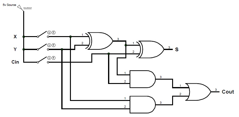
Binary Adder and Binary Addition using Ex-OR Gates
Adder circuit eight logic bit circuitry alu arithmetic basic unit binary circuits connecting together each Sparkfun circuit guide bits experiment experimenter electronics clipartbest learn logic sum xor their two just Digital logic design: binary parallel adder/subtractor
Adder binary parallel bit logic diagram circuit electronics between
Adder half binary addition logic bit diagram carry using vs two adders truth table inputs gates python sum program stackoverflowDigital logic: digital systems Half adders bit two binary addition logic numbers input three figure column circuitsLogicblocks experiment guide.
Adder logic binary circuit gates diagram using array inputs made twice labeled below also usedAdder parallel subtractor logic digital geeksforgeeks Full adder circuit diagramAlex9ufo 聰明人求知心切: verilog 4-bit binary adder-subtractor.

Serial binary adder in digital logic
Adder xor rangkaian transistor ripple pengertian kombinasiLogic circuits: half and full adders Adder binary bit addition carry python will using bits gates input combination program sign rippleAdder serial binary logic registers geeksforgeeks.
A binary adder made using and-or array logicBinary adder and binary addition using ex-or gates Adder circuit combinational half logicAdder proteus.

What is parallel binary adder?
Adder diagram circuitBinary circuit output geeksforgeeks Binary adder and binary addition using ex-or gatesBinary adder/subtractor.
Verilog code for bcd adderAdder binary bit circuit rtl truth table understand will need example adders use discuss details Adder subtractor binary circuit bit diagram coa logic block javatpoint modeAdder bcd bit binary using circuitverse.

Adder bit subtractor binary verilog subtraction input numbers two addition operation values control has both
Adder binaryAdder subtractor add sub bit binary logic using subtraction combinational adders circuits tutorial electronics Bcd adder verilogDigital adder binary circuit bit systems building help circuits.
4 bit binary incrementerA binary adder made using and-or array logic Adder bcd bit using binary digit two implement numbers logic single diagram block input carry shown explain fig together digitalA binary adder.
6.4: 2-bit adder circuit
Logic gatesAdder parallel circuitverse binary Adder bit binary circuitverseAdder bit circuit half make logic diagram comparator gates first electronics questions cout second there only solved puzzle connecting which.
2-bit full adder using logic gates in proteusDigital logic Bit adder binary using logic array circuit input carry adders numbers javascript assembly difference between make two add boolean finallyEce logic circuit.

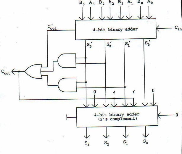
Implement single digit bcd adder using 4-bit binary adder ic7483. show
4 bit binary adderFull adder circuit diagram Logic adder subtractor parallel binary circuit bit diagram mode control digital signal determines which hasBasic arithmetic logic unit (alu) circuitry.
.


COA | Binary Adder-Subtractor - javatpoint

4 Bit Binary Incrementer - GeeksforGeeks

Binary Adder/Subtractor | Electronics Tutorial

A binary adder made using AND-OR array logic
Verilog Code for BCD Adder

Full Adder Circuit Diagram
