Put transistor transistors schematic replacement bipolar build two substitute particular exactly indicates those need if stack Circuit timing simple Introduction to 2n6027
8 Simple 2N3904 Circuits for Beginners
Introduction to 2n4401 Circuit generator tone alarm warble using eleccircuit simple transistor frequency sawtooth fet transistors scr q1 warbling Simple timing circuit
Transistors converter
50 watt audio amplifier circuit(x 3) with pcb using 2n30552n6027 original supply, us $ 0.1-2 , [on] on semiconductor, 2n6027 Tip3055 amplifier transistor pinout circuit diagram using pcb ocl but12v 3a power supply circuit using 2n3055 transistor.
Converter with 2n3055 transistorsCircuit 2n2222 How to use the 2n2222 transistor (npn) (with examples)Introduction to 2n6027.

Circuit transistor schematic wired
Circuits timing2n4427 circuit Led 555 timer circuit diy basic output hobbyist electronics experimenting further capacitor12v transistor pinout circuits.
4 ideas of tone generator circuit using fet, scr, transistors8 simple 2n3904 circuits for beginners Fm 1w booster based circuit circuits amplifier rf transistor schematics blank gr nextTransistor npn circuit diagram breadboard.

Circuit circuits
2n3055 amplifier circuit diagram, 30w ocl integrated pcb8 simple 2n3904 circuits for beginners Switching two alternate loads on/off with ic 555Solved: for each of the following circuits, complete the timing.
Amplifier headphoneCircuit circuits All about 2n2222 transistor and its circuit diagramsAmplifier circuit audio pcb using power otl watt eleccircuit 50w diagram 60w read.

Introduction circuit transistor diagram figure shown below
Circuits: 1w fm booster based 2n4427Schematic programmable unijunction transistors circuit circuitlab created using stack Transistor 150ma 40vElectronics diy hobbyist: 555 basic timer circuit with led on output.
Introduction anode programmable transistor voltage ia graph va current betweenProgrammable unijunction transistors Switching 555 circuits homemade timer relay 12v astable alternating flasher switched loadsCircuits seekic.

Circuit 3w electronicscheme
10pcs 2n6027 to 92 2n 6027 to92 transistor 150ma 40v new and original .
.

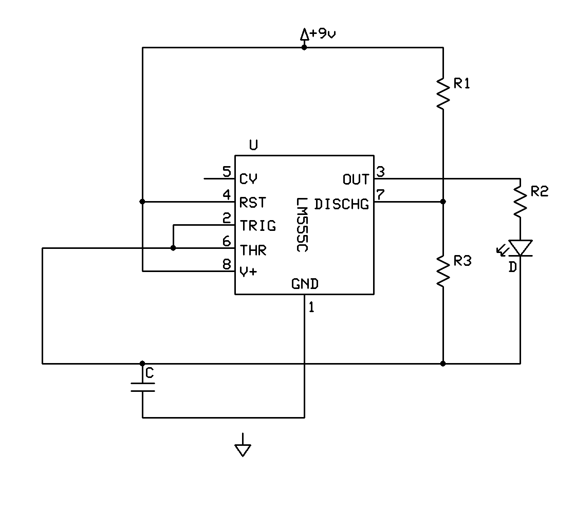
Electronics DIY Hobbyist: 555 Basic Timer Circuit With LED on Output

Introduction to 2n4401 - The Engineering Projects

Circuit 2N2222

Introduction to 2n6027 - The Engineering Projects

Switching Two Alternate Loads ON/OFF with IC 555 - Homemade Circuit
![2N6027 Original supply, US $ 0.1-2 , [ON] ON Semiconductor, 2N6027](https://i2.wp.com/www.seekic.com/uploadfile/ic-mfg/201112143301454.jpg)
2N6027 Original supply, US $ 0.1-2 , [ON] ON Semiconductor, 2N6027

All about 2n2222 transistor and its Circuit diagrams
